Turbine Pumps
Batescrew turbines are of conventional ‘mixed flow turbine’ design, in which energy is imparted to the flow by impellers utilising the dual components of centrifugal force and vane reaction, an efficient arrangement for pumping at medium to high heads.
+ BROCHURE.
You can download our Turbine brochure here
+ DETAILED PUMP CUTOUT
+ PRESSURE OUTPUT
Delivery pressure is increased by adding multiple impeller stages to a pump, with each extra stage proportionately increasing pressure output and power consumption. Adding impeller stages does not increase flow rate.
The maximum pressure achievable depends on the number of stages which may be safely added to each pump model. The maximum number of stages (therefore maximum pressure) is stated on the Impeller Performance Curve for each pump
+ FLOW RATE
Capacity of pumps in the Batescrew Turbine range varies from 5 litres/second to 1600 litres/second.
The output of any pump may be varied, within limits, by changing rotational speed, in which case impeller performance curves should be consulted to ensure performance will remain within an acceptable efficiency range.
+ VERTICAL and ANGLE APPLICATIONS
These pumps may be used vertically, as bore pumps, or in angle applications on river banks and storage dams.
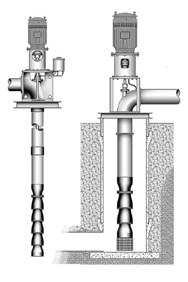
Vertical Application
Basic 'wet end' assemblies are fitted with various types of column and discharge head, allowing vertical turbines to be used in bores, sumps, rivers or dams. Several arrangements of screwed and flanged column are available.
COST comparison with Angle Application pumps.
- A vertical pump generally costs less than the equivalent angle pump.
- Cost of supporting structure for river installation may be higher for a vertical pump.
- Excavation cost for a sump of over six metres depth is likely to be excessive, particularly if a different system layout would permit use of an angle application pump.
Discharge may be above or below ground level and extended drive columns are available, if required, to keep motors and thrust bearings above flood level.
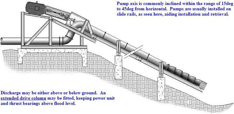
Angle Application
On a river bank, this configuration presents the least obstruction to river flow, causes less bank disturbance and requires less infrastructure than would a vertical pump. Convenient installation and retrieval from river-bank and water storages.
+ DRIVE OPTIONS
Drive Options for Angle and Vertical Application Pumps
The following drive arrangements are applicable to both
Axial Flow and Turbine pumps.
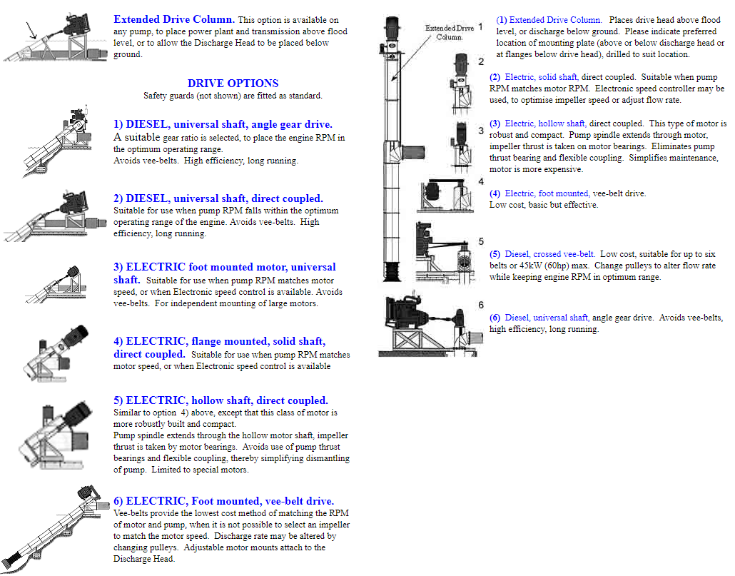
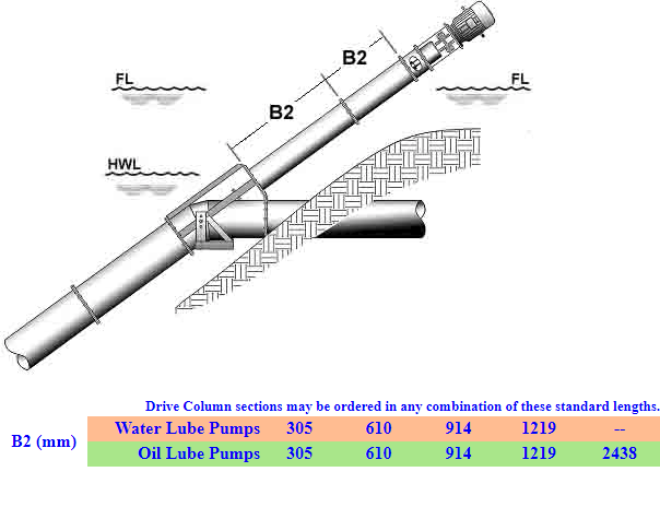
+ EXTENDED DRIVE COLUMN
To raise thrust bearings and drive unit above flood level. See table below for standard lengths.
Thrust bearings are located at top of drive column.
Thrust bearings must be kept above flood level. Cooling water is normally circulated from the pump discharge to a water-jacketed bearing housing at the top of an extended drive column.
If there will be insufficient pressure for cooling water to reach the housing, a special air-cooled housing or a separate thermo-siphon water cooling system should be used. Please consult Batescrew Technical Services Department for details.
Line shaft bearings for extended drive column.
WATER LUBRICATED Line shaft bearing carriers are held between the flanges along the length of the extended column. The maximum length of each column section is therefore limited to 1.22 metres (4ft), with multiple standard sections being used to make up the required overall length.
As these bearings are water-lubricated, there must be adequate internal pressure for water to reach the top bearing. Failing this, options include: 1) External flushing water system or 2) Grease-lubricated roller bearings in the upper sections. Please consult the factory for details.
OIL LUBRICATED Bronze bearings are carried in an internal lube-tube, therefore longer external column lengths may be used, as per the table below.
+ LINE SHAFT LUBRICATION
These pumps are generally line shaft driven, with bearings lubricated either by 1) Water; 2) Oil; or 3) Fresh Water Flush.
OIL LUBRICATION extends bearing life and is used when grit or suspended solids are to be pumped. Lubricant is a bio-degradable vegetable oil, drip-fed to an enclosed shaft running in bronze bearings. The enclosing lube-tube is galvanized externally and internally to protect lubricant from contamination by products of condensate corrosion. Adjustable drip feeders are fitted as standard. Solenoid drippers are used with automatic-start systems to enable lubrication to begin fifteen minutes before pump start.
WATER LUBRICATION is an option if the supply is sand-free potable water. The pumped medium lubricates an exposed stainless steel line shaft, running in EPDM rubber bearings. (Batescrew petrol pumps use a similarly product-lubricated system with synthetic bearings.)
ENVIRONMENTALLY SENSITIVE LUBRICATION (Fresh Water Flush) This Batescrew developed system prevents contamination of natural waterways by lubricating oil, even though this oil may be bio-degradable. When water quality is unsuitable for lubrication and would normally dictate use of oil, the alternative of Fresh Water Flush provides clean lubricating water to stainless shafts running in EPDM rubber bearings, all enclosed in a sealed lube-tube. Two variations are in use: a) When the pumped water is non-aggressive, but contains suspended solids, filtered water is fed from the pump discharge to the line shaft bearings. b) When the pumped water is highly acidic, alkaline, or otherwise aggressive, clean fresh lubricating water is supplied from an independent reservoir.
In both cases, provision is made for lubricating water to be available at the bearings before the pump is started.
+ MORE BEARINGS per PUMP
Spacing between line shaft bearings on Batescrew pumps is restricted to a maximum of 1.22 metres. Close bearing spacing ensures design stress of drive shafts is in compliance with 'Fixed Fire Pump Standard AS2941'. As a result, our pumps may have more line shaft bearings than are found in pumps from other manufacturers.
+ Water-cooled Thrust Bearing.
Thrust bearings, located at the top of the drive column, are held in a water-jacketed cast iron housing. Cooling water is tapped from the pump discharge, circulates through the bearing housing and is returned to the discharge line. If a pump has a long drive column extension (as for underground discharge) and low operating head, there may be insufficient pressure for cooling water to reach the thrust bearing. In such cases a special air-cooled bearing assembly or a separate thermosyphon cooling system may be specified.
Seven thrust bearing assemblies are available, matching pump power ratings from 18 kW (25hp) to 740 kW (992hp).These units are fitted to both Axial Flow and Turbine pumps, Thesmallest bearing, No.1, is air cooled, while all larger sizes have water cooled housings,for which pressurised cooling water is tapped from and recirculated to the discharge head.Sizes, power ratings and replacement parts are listed in the table at the foot of this page.
Impeller Performance Curves
Performance curves are generated from actual test data and describe the characteristics of individual impellers under test but do not directly provide performance figures to be expected of a pump. Curves are used for impeller comparison and selection.
To calculate expected pump performance, a true value for Total Dynamic Head is needed, found by adding all of the dynamic losses within a system, to a known value for Static Head.
Dynamic losses are influenced by the various flow velocities occurring at different points in a system and include the following:
All losses occurring in pipes, bends etc. leading to a sump.
The influence of sump design on pump intake loss.
Pump losses arising in wet end, column and discharge head.
All discharge-end losses in pipes, bends, valves, outlet bubblers etc.
Turbine Dimensions
Click to view larger image
Typical galvanised fabricated head for a Batescrew turbine, as used with oil or fresh-water-flush lubrication of the line shaft bearings. There are slight variations to this design on larger pumps, while small models in the Batescrew range have cast heads in aluminium, cast iron, bronze or stainless steel.
The head and vertical column are often not of the same diameter as the wet end assembly, heads are therefore listed below by size (nominal diameter of bore) rather than pump model. Column and discharge head are usually of the same diameter. If necessary for clarity, the dimension tables will contain links to additional drawings.